rockus.at: Ariadne 2
rockus.at / Amiga / Ariadne 2
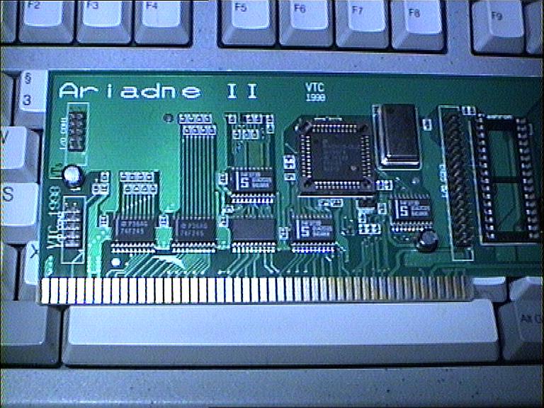 Ariadne 2 I/O connectors
|
For a long time now I wanted to know what the additional I/O connectors on
VillageTronic's Ariadne 2 can be used for and how to access them.
Unfortunately several tries to get hold of documentation only yielded in a
"Not done yet." So, "several nights ago" I got bored [well, as bored as an
engineer can get with a load of hardware in front of him :)], so I traced
some lines, read some datasheets, did some coding and got high on the
smell of burnt skin and vapourised tin. The result: some interesting
tid-bits and a blinking LED.
For a start here's the list of signals on the I/O connectors:
As can be seen, there is no chip select line implemented for these connectors. The proper addresses would have to be decoded on an add-on itself. /IOR, /IOW, /SMEMRB and /SMEMWB are only asserted if addresses are accessed within the 64KB I/O space the Ariadne 2 is configured in. Tests have shown that the rtl8019 registers are present in the lower 32KB of the I/O space several times. They show up at 0x0600, 0x0e00, 0x1600, 0x1e00, ..., 0x7600 and 0x7e00. All but the first seem to be mere mirrors of the first occurance. In fact, the Linux/m68k driver (line 73) for the Ariadne 2 accesses the rtl8019 from 0x0600 onwards. There is a LhA-Archive of source and binary for a short quick&dirty test program available, relevant snippets from the code are explained below. The definitions necessary to find the proper device structures using FindConfigDev(): #define VillageTronic 2167 // manufacturer #define AriadneII 202 // product A part of a structure (filled with paddings) to access page0 of rtl8019's registers. Of special interest are rtl8019ID0 and rtl8019ID1 as these are supposed to always read 0x70 and 0x50 respectively, which comes in very handy in trying to figure out register layout and addressing schemes:
struct rtl8019
{
        UBYTE rtlCR;
        UBYTE pad0;     // rtl8019 connected to even addresses
        UBYTE rtlCLDA0;
        UBYTE pad1;
        UBYTE rtlCLDA1;
        UBYTE pad2;
        UWORD pad[7];
        UBYTE rtl8019ID0;
        UBYTE pad10;
        UBYTE rtl8019ID1;
        UBYTE pad11;
};
To retrieve the addresses to access the registers the following equations will help as usual, where confDev contains the pointer to the I/O space as returned by FindConfigDev(): #define RTL8019offset 0x600 AriadneIIBase = (ULONG)(confDev->cd_BoardAddr); rtl8019 = (struct rtl8019 *)((ULONG)(AriadneIIBase) | RTL8019offset); The above is to access the rtl8019 chip present on the Ariadne 2. But more interesting should be information on how to use the I/O connectors. Judging by the results retrieved from the small test program above, there is supposed to be 32KB (at offsets 0x8000...0xffff) of address space easily addressable and usable for hardware connected to the I/O pins of this nice card. There are 14 address lines (A1...A14) available on I/O CON3, which resolves to 32KB addressable space (16bit wide). /IOR and /IOW adress the lower 32KB of the 64KB Zorro-II I/O space, while the upper half of the I/O space is addressed using /SMEMRB and /SMEMWB. This then resolves in the following memory map:
Note: After a reboot the Amiga appears to try to write some location in the upper memory area. I guess this is to determine if there is a Flash or SRAM available there. With this in mind it is perfectly possible now to attach some cute little devices to these ports. If anyone out there wants to add to this page or has some comments, feel free to drop me an email. |
||||||||||||||||||||||||||||||||||||||||