rockus.at: Ariadne 2 clock-port
rockus.at / Amiga / Ariadne 2 clock-port
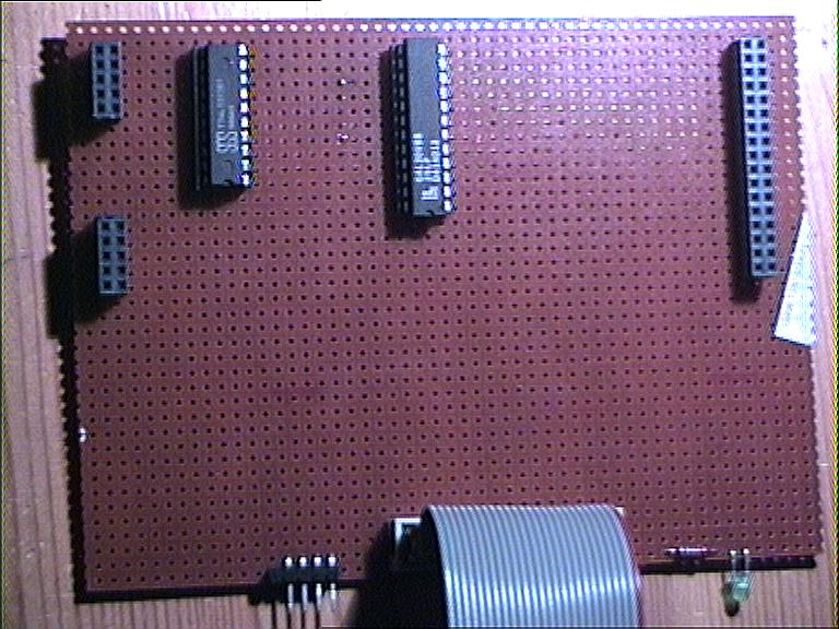 Ariadne 2 clock-port top
 |
The tedious task of reverse engineering the
Ariadne 2 network adapter has finally paid off. I successfully
connected my hardware mp3 decoder PROmp to an
Ariadne 2 using an interface that behaves exactly the same as an A1200
style clock-port, electrically. This can be understood as a proof of
concept that this card can offer additional value, despite lack of
official information.
The interface in itself is really simple as only a suitable chip select signal has to be generated by a bit of glue logic. Obviously, software drivers have to be patched or re-written to recognise hardware attached to that port. For patching it is sufficient to know the offset into configuration space and register spacing and the new port can be put to good use. As of now, there have been no tests with "real", i.e. not made by myself, clock-port devices available on the market. I hope to be able to test both my own device (PROmp3) as well as commercially available devices on both a "true" clock-port in an A1200 or the one present on an X-Surf (simply because I already own one, not because of any technical reasons) and my version of a clock-port in the near future. I'll add schematics and more detailed programming information in a bit. Up till then, there is some preliminary information below. The definitions necessary to find the proper device structures using FindConfigDev(): #define VillageTronic 2167 // manufacturer #define AriadneII 202 // product A part of a structure (filled with paddings) to access page0 of rtl8019's registers. Of special interest are rtl8019ID0 and rtl8019ID1 as these are supposed to always read 0x70 and 0x50 respectively, which comes in very handy in trying to figure out register layout and addressing schemes:
struct rtl8019
{
        UBYTE rtlCR;
        UBYTE pad0;     // rtl8019 connected to even addresses
        UBYTE rtlCLDA0;
        UBYTE pad1;
        UBYTE rtlCLDA1;
        UBYTE pad2;
        UWORD pad[7];
        UBYTE rtl8019ID0;
        UBYTE pad10;
        UBYTE rtl8019ID1;
        UBYTE pad11;
};
To retrieve the addresses to access the registers the following equations will help as usual, where confDev contains the pointer to the I/O space as returned by FindConfigDev(): #define RTL8019offset 0x600 AriadneIIBase = (ULONG)(confDev->cd_BoardAddr); rtl8019 = (struct rtl8019 *)((ULONG)(AriadneIIBase) | RTL8019offset); The above is to access the rtl8019 chip present on the Ariadne 2. But more interesting should be information on how to use the I/O connectors. Judging by the results retrieved from the small test program above, there is supposed to be 32KB (at offsets 0x8000...0xffff) of address space easily addressable and usable for hardware connected to the I/O pins of this nice card. There are 14 address lines (A1...A14) available on I/O CON3, which resolves to 32KB addressable space (16bit wide). /IOR and /IOW adress the lower 32KB of the 64KB Zorro-II I/O space, while the upper half of the I/O space is addressed using /SMEMRB and /SMEMWB. This then resolves in the following memory map:
Note: After a reboot the Amiga appears to try to write some location in the upper memory area. I guess this is to determine if there is a Flash or SRAM available there. With this in mind it is perfectly possible now to attach some neat little devices to these ports. If anyone out there wants to add to this page or has some comments, feel free to drop me an email. |